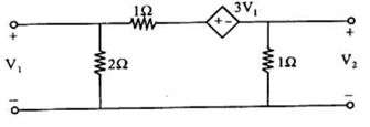
Important RGPV Question
EC-305 Network Analysis
III Sem, EC

UNIT-1 Introduction to Circuit Theory

UNIT-2 Network Graph Theory

UNIT-3 Network Theorems

UNIT-4 Transient Analysis & Laplace Transform

UNIT-5 Two Port Parameters
UNIT 1
Introduction to Circuit Theory
Q. 1) State and prove RLC parallel resonance.
(RGPV June 2023)
Q. 2) State and explain Kirchhoff's voltage and current law wit an example.
(RGPV Nov 2022)
Q. 3) A series RLC circuit takes a maximum current of 0.3 A at 200 V, 50 Hz. If the voltage across the capacitor is 290V at resonance. Determine R,L,C and Q.
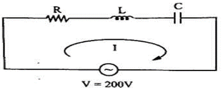
(RGPV Nov 2022)
Q. 4) Draw the parallel resonant circuit and derive the expression for resonant frequency.
(RGPV Nov 2022)
Q. 5) Find VAB

(RGPV Dec 2020)
Q. 6) Draw the duality of given circuit

(RGPV Dec 2020)
Q. 7) Find the current i1 and i2 using Mesh analysis
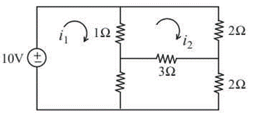
(RGPV Dec 2020)
Q. 8) Distinguish between :
i) Active and Passive elements
ii) Loop and Mesh
iii) Independent and dependent source
(RGPV Dec 2020)
Q. 9) a) State and explain KVL with the help of suitable example. b) Explain RLC series resonance circuit. RLC
c) Define characteristic impedance and propagation constant
(RGPV Dec 2020)
Q. 10) Explain in detail the following :
i) Double tuned circuit
ii) Single tuned air core transformer.
(RGPV June 2020)
Q. 11) Two coupled coils have self inductances L1=10mH and L2=20 mH. The coefficient of coupling is 0.75 in air. Find voltage induced in the second coil and flux of the first coil provided second coil has 500 turns and circuit current is given by i1=2sin 314t amps.
(RGPV June 2020)
Q. 12) In a RLC series circuit, determine the expression for the resonant frequency and expressions for half power frequencies and bandwidth.
(RGPV June 2020)
Q. 13) Explain the following:
i) Phasor.
ii) Resonance.
iii) Vector
(RGPV June 2020)
Q. 14) Give the characteristics of circuit elements in terms of linearity and time dependent nature.
(RGPV Nov 2019)
Q. 15) Determine the current flowing in the branch AB of the circuit below
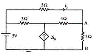
(RGPV Nov 2019)
Q. 16)
State and prove Kirchhoff's Laws KCL and KVL.
(RGPV Nov 2019)
Q. 17) Explain series and parallel resonance. What are their similarities and dissimilarities?
(RGPV Nov 2019)
Q. 18) Determine the current I in the circuit of figure using
i) Mesh analysis
ii) Nodal analysis
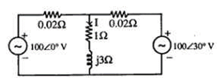
(RGPV Nov 2018)
Q. 19) Classify different types of voltage and current source. Also draw their respective symbols.
(RGPV Nov 2018)
Q. 20) Explain the principle working of RLC series resonance.
(RGPV Nov 2018)
Q. 21) Draw the dual network of following circuit figure
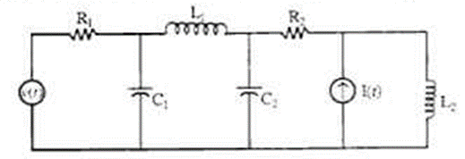
(RGPV Dec 2016)
Q. 22) Write the loop equations of magnetically coupled circuit shown in figure .
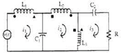
(RGPV Dec 2016)
Q. 23) a) Explain the current division in a parallel circuit of three unequal impedances.
b) Write a note on co-efficient of coupling in a magnetic circuit.
c) Determine the expression for Bandwidth in a series resonance circuit.
d) Compute the voltage V of the coupled circuit given below
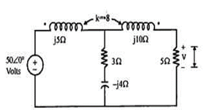
Or
A series RLC circuit consists of a resistance of 1 k2 and an inductance of 100 mH in series with a capacitance of 10 pF. 100 volts is applied as input across the combination determine :
i) The resonant frequency
ii) Maximum current in the circuit
iii) Q factor of the circuit
iv) The half power frequencies
(RGPV June 2016)
Q. 24) Derive the equation for Equivalent inductance, when two inductors are coupled in series opposing and mutual inductance exists between them.
(RGPV Nov 2022)
UNIT 2
Diode Circuits
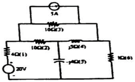
Q. 1) For the network shown in fig write the tie set matrix for the twigs (2, 4, 5) and determine the loop currents and branch currents for the same.
(RGPV June 2023)
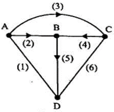
Q. 2) Define Incidence Matrix for the graph shown in Figure. Find the complete Incidence Matrix.
(RGPV Nov 2022)
Q. 3) Define and explain the following with an example:
i) Graph and Subgraph
ii) Oriented Graph
iii) Tree of a Graph
iv) Twigs and Links
(RGPV Nov 2022)
Q. 4) Define the terms with suitable diagram
i) Planar and non-planar graph
ii) Tree and Co-tree
(RGPV Dec 2020)
Q. 5) For the network shown below, draw the oriented graph.

(RGPV Dec 2020)
Q. 6) Define the following with figure
i) Tie-set matrix
ii) Cut-set matrix
(RGPV Dec 2020)
Q. 7) With the help of an example explain the following for a network graph:
a) Complete incidence matrix and reduced incidence matrix
b) Tie-set and Tie-set schedule
c) Cut-set and Cut-set schedule
(RGPV June 2020)
Q. 8) With the help of examples explain.
i) Tree
ii) Tree branch and links
iii) Incidence matrix
(RGPV Nov 2019)
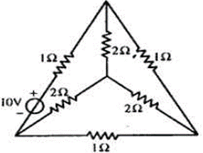
Q. 9) For the network shown below draw the graph and write down the tie-set matrix.
(RGPV Nov 2019)
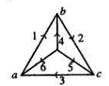
Q. 10) Consider the graph shown in figure. Select a tree with twigs (4,5,6), for this tree write down the tie set matrix and cut set matrix.
(RGPV Nov 2018)
Q. 11) What is a sub graph of a graph? How we can obtain the rank of a graph?
Explain following terms with reference to network topology:
i) Tree and Co-tree
ii) Node and Branch
iii) Twig and Link
State and explain the Norton's theorem.
Find the Thevenin's equivalent across a-b terminals of the circuit given below:
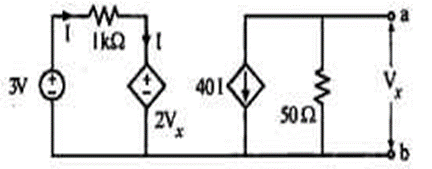
OR
For the circuit given below determine the load impedance Z that maximizes the average power drawn from the circuit. Also determine the value of maximum power.
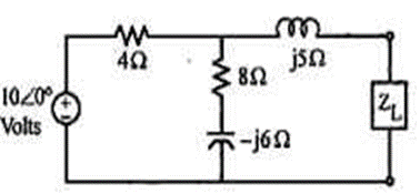
(RGPV June 2016)
Continue Reading

UNIT 3
Fundamentals of BJT
Q. 1) In the circuit Of fig at time t0, after the switch S was closed, it is found that V2 = + 5v. Determine the value of

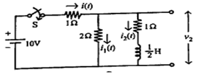
(RGPV June 2023)
Q. 2) In the circuit of fig, the switch S is open and the circuit reaches a steady state. At t=0 the S is closed. Find the current in the inductor for t > 0.
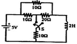
(RGPV June 2023)
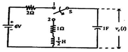
Q. 3) In the circuit of fig-3, switch S is in position 1 for a long time and moved to position 2 at t= 0. Find the voltage across the capacitor vc(t) for t > 0.
(RGPV June 2023)
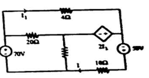
Q. 4) By super position theorem calculate current I in the circuit shown in fig
(RGPV June 2023)
Q. 5) Find the norton equivalent circuit across terminal AB the circuit shown in fig

(RGPV June 2023)
Q. 6) State and prove maximum power transfer theorem.
(RGPV June 2023)
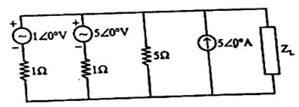
Q. 7) For the circuit shown in fig, find the current in the load impedance, ZL=(2+j4)Ωusing Millman's theorem.
(RGPV June 2023)
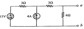
Q. 8) Find the Norton's equivalent circuit for the following circuit
(RGPV Nov 2022)
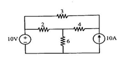
Q. 9) Find the voltage drop across 32 resistor by Superposition theorem.
(RGPV Nov 2022)
Q. 10) State and explain the Tellegen's theorem with suitable example.
(RGPV Nov 2022)
Q. 11) For the circuit, find the current across 2Ω resistor using superposition theorem.

(RGPV Dec 2020)
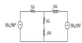
Q. 12) Obtain the current through (3 +j4) Ω using with 50 ∠ 90° suitable theorem.
(RGPV Dec 2020)
Q. 13) A voltage source V1 whose internal resistance is R1 delivers power to a load R2+jX2 in which X2 is fixed but R2 is variable. Find the value of R2 at which the power delivered to the load is a maximum
(RGPV June 2020)
Q. 14) State and prove Norton's theorem. Show with example, how this theorem is used for circuit analysis.
(RGPV Nov 2019)
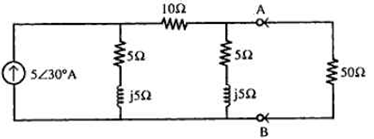
Q. 15) Obtain Thevenin's equivalent network of the network shown in figure at terminal AB. Also calculate the power delivered to a load of 50 Ohms if connected at AB.
(RGPV Nov 2019)
Q. 16) Calculate the current in the 62 resistor of the circuit of figure by
i) Thevenin's theorem
ii) Super position theorem

(RGPV Nov 2018)
Q. 17) Determine the value of R, to be connected across AB in figure, for maximum power transfer. Also calculate the maximum power absorbed by RL.

(RGPV Nov 2018)
Q. 18) State and prove Millman's Theorem and Tellegen's Theorem
(RGPV Nov 2018)
Q. 19) Verify reciprocity theorem for the network shown in

(RGPV Nov 2018)
Q. 20) By superposition theorem calculate current I in the circuit shown in figure .

(RGPV Dec 2016)
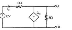
Q. 21) Find the Norton equivalent circuit across the terminal AB of the circuit shown in figure .
(RGPV Dec 2016)
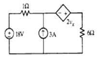
Q. 22) Calculate the current in the 652 resistor of the circuit shown in figure using Thevenin theorem.
(RGPV Dec 2016)
Q. 23) State and prove maximum power transfer theorem.
(RGPV Dec 2016)
UNIT 4
Signal Analysis
Q. 1) In the circuit of fig at t = 0 the switch is closed Determine the voltage across the capacitor by applying Laplace transform. Assume the initial voltage across the capacitor as 2V. Also draw the S-domain representation of the circuit.

(RGPV June 2023)
Q. 2)
In circuit of fig the pulse shown is applied as v(t) determine i(t).

(RGPV June 2023)
Q. 3) Find the value of i(0+) using the initial value theorem for the function
I(s) (2s+3)/[(s+1)(s+3)]
(RGPV Nov 2022)
Q. 4) In the network shown in figure below, the switch K is moved from position 'a' to 'b' at t=0. Find the Particular solution for Current i(t).
(RGPV Nov 2022)
Q. 5) For the waveform shown in figure below. Write the expression and find the Laplace transform.
(RGPV Nov 2022)
Q. 6) Write the Laplace transform of the following
i) e-at u (t)
d (r (t)) dt
(RGPV Dec 2020)
Q. 7) Explain the transient analysis of series RL circuit for DC excitation
(RGPV Dec 2020)
Q. 8) Derive the expression for R and L for t > 0
(RGPV Dec 2020)
Q. 9) Obtain the Fourier series representation of the period waveform shown in figure
(RGPV June 2020)
Q. 10) How do you describe the transient in RC circuit? Explain.
(RGPV Nov 2019)
Q. 11) For the RL series circuit shown in figure. The switch S is closed at t=0. Find the current i(t).
(RGPV Nov 2019)
Q. 12) Find Laplace transform of following functions:
i) Impulse function
ii) Gate function
(RGPV Nov 2019)
Q. 13) State and prove Initial and Final value theorem.
(RGPV Nov 2019)
Q. 14) In the circuit of figure at time to, after the switches was closed, it is found that v₂ = +5v. You are required to determine the values of i(to) and di2 (to).
dt
(RGPV Nov 2018)
Q. 15) In the circuit of figure after the switch has been in the open position for a long time it is closed at t=0. Find the voltage across the capacitor.
(RGPV Nov 2018)
Q. 16) Find the current i(t) for > 0 for the circuit of figure. Assume that the circuit has reached steady state at r = 0. Switch is closed at t=0
(RGPV Nov 2018)
Q. 17) In the circuit shown in figure the switch S is closed at 10 connecting a source e-t to the RC circuit. At t=0, it is observed that the capacitor voltage has the value vc(0)=0.5V. Determine va(t).
(RGPV Dec 2016)
Q. 18) In the circuit of figure , after the switch has been in the open position for a long time, it is closed at t = 0. Find the voltage across the capacitor.
(RGPV Dec 2016)
Q. 19) In the circuit of figure at time to, after the switch S was closed, it is found that v₂ = +5V. It is required to determine the value of i₂(to) and
di2 (to)
dt
(RGPV Dec 2016)
Q. 20) In the circuit of figure 9 the switch S is in position 'a' for a long time. At = 0 the switch is moved from 'a' to 'b'. Find v2(t) using numerical values given in the circuit. Assume that the initial current in 2H inductor is zero.
(RGPV Dec 2016)
Q. 21) Determine the Fourier series expression of the waveform shown in figure .
(RGPV Dec 2016)
Q. 22) a) Discuss the initial conditions of voltage and current in inductor and capacitor.
b) Explain the effect of the time constant on the current i(t) in a RL series circuit.
c) Obtain the RMS voltage of three sources connected in series: V₁ =50 sin ῳt;
V₂=80 sin (ῳt+50°); V3=100 sin (ot-60°)
d) For the circuit given below derive the expression for i(t) and VC(t) when the switch is moved from position I to 2 at t=0.
OR
For the circuit given below initially switch is kept open for a long time and closed at t=0. Find the expression for Vc(t) and sketch it against t.
(RGPV June 2016)
Q. 23) a) Define and explain the unit impulse function.
b) Write short note on half wave symmetry of a function f(t).
c) Explain trigonometric form of a Fourier series.
d) Obtain the Fourier transform of a unit step function.
OR
Obtain the Fourier series expansion of the waveform given below.
(RGPV June 2016)
UNIT 5
FET Construction
Q. 1) Obtain the Z and Y parameters of the network shown in fig
(RGPV June 2023)
Q. 2) Find the Y-parameter of the circuit as shown in figure below
(RGPV Nov 2022)
Q. 3) Derive the expression for the relation between impedance and admittance matrix.
(RGPV Dec 2020)
Q. 4) Find the z-parameter
(RGPV Dec 2020)
Q. 5) Derive equation for decay of current in R-L circuits. Discuss the role of time constant.
OR
a) Explain Z-parameters. How will you convert Z-parameters in to Y-parameters.
b) Determine the ABCD (transmission) parameters for the network shown in figure.
(RGPV June 2020)
Q. 6) a) Obtain the relationship between ‘h’ and ‘y’ parameters of a two-port network.
b) Determine the two-port network that is represented by the following Z-parameters
(RGPV June 2020)
Q. 7) Write Z parameters in terms of transmission parameters.
(RGPV Nov 2019)
Q. 8) Derive the condition of symmetry for ABCD parameters.
(RGPV Nov 2019)
Q. 9) Calculate the Z and Y parameters of the network shown in figure. Also determine if the network is reciprocal and symmetrical or not
(RGPV Nov 2018)
Q. 10) Determine the Z-parameters for the network shown in figure .
(RGPV Dec 2016)
Q. 11) Determine the Y-parameters of the network shown in figure .
(RGPV Dec 2016)
Q. 12) a) Define poles, zeros and pole zero plot.
b) What is meant by an all pass function?
c) Derive the condition of reciprocity for h parameters.
d) Determine the Y parameters of the network given below.
OR
Determine the driving point impedance of the network given below.
(RGPV June 2016)
-- Best of Luck for Exam --


